RGB LED Shield
a Ben Combee/HTINK project
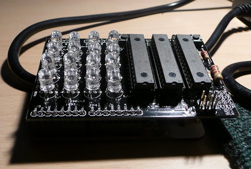
This Arduino-compatible shield uses three TI TLC5940 PWM LED driver ships to drive a 4x4 array of RGB LEDs. Each color is controlled by a different chip so you can adjust the reference resistors for the appropriate current. This also includes mounting positions for for three general-purpose buttons that are connected to ground, and a reset button. The TLC5940 chips are not directly connected to any Arduino pins, but a header is provided for you to make a manual connection depending on the needs of your sketch.
This board is a version of the circuit used at the first HTINK workshop on March 14th, 2009 at Bug Labs in New York City.
This project was once available as a kit from Seeed Studio, but it has been discontinued. They still have their listing up. Ben no longer has PC boards available, but you can use the board layout files to make your own batch using services like Seeed's Fusion PCB or OSH Park.
Programming the RGB LED Shield
To program your Arduino to control the RGB LED shield, you first need to install the tlc5490arduino library from http://code.google.com/p/tlc5940arduino/. Do this by downloading the ZIP file from the site, unpacking the TLC5490 folder, and putting it into your Arduino IDE's hardware/libraries folder. You'll then need to modify the tlc_config.h file to change the line
#define NUM_TLCS 1
to read
#define NUM_TLCS 3
since there are three TLC5490 ICs in this circuit connected in series.
Here are a few example sketches that will use this library to make different patterns.
- TLC_wavy.pde, Eric Moore
- TLC_box_1.pde, Ben Combee
- TLC_box_2.pde, Ben Combee
- TLC_arrows2.pde, Ben Combee
On the shield, the four LEDs at the corners are labeled with their X,Y coordinates: "1,1", "1,4", "4,1", and "4,4". The formula to turn a coordinate into a LED number is (X - 1 + (Y - 1) * 4).
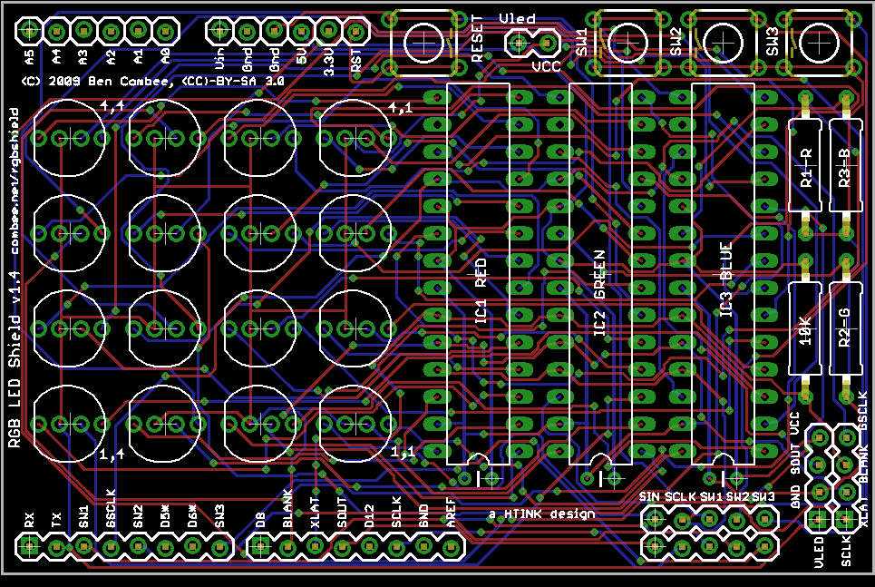
Version 1.4
This version has some major changes from the original 1.1 board.
- Fixed the DCPRG signal. In the 1.1 shield, this was tied to GND instead of VCC. This prevents you from loading dot correction information into the TLC chips.
- Added a 10K resistor between BLANK and VCC. This pulls up the BLANK line when the Arduino isn't asserting it, keeping the LEDs from lighting when there's no control signals (like during reset).
- Added a default header parallel to the TLC signal header so you can just use jumper wires to give the shield a default wiring hookup. You also can populate this with a 2x8 header and then use plastic jumpers for this.
- Disconnected the power net for the LEDs from the board VCC and provide a two pin connector to connect them together. This would allow running the LEDs at a different voltage if desired.
- The GSCLK, BLANK, and XLAT signals are now all hard-wired to Arduino pins D3, D10, and D9 respectively. This is because the TLC5940 library uses those pins for their special timer properties, so they can't be reassigned.
- Added an 2x4 output header that allows chaining a second board to the first one, with all the TLC5940 control pins, power, and ground provided.
- Eliminated the extra holes that were provided to wire up signals and replaces them with silkscreen labels for the Arduino signals.
- All of the resistors are moved to the edge of the board, making it easy to hook up potentiometers to figure out the brightness settings for each channel
- All ICs and resistors are labeled with the color channel they control.
- ERRATA: Vled and Vcc are labeled backwards on JP11. Since you usually just connect these together, there's no real problem, but if you want to power the LEDs using a separate voltage source, connect to the proper pin.
- ERRATA: The GSCLK and BLANK labels are reversed on the Arduino shield connector. The labels on the piggyback connector, JP21, are correct.
RGB_LED_Shield_1.4.zip - includes schematic, board image, and design files for Eagle CAD
Parts List
- 16 common-anode RGB LEDs (LED11-LED44)
- 3 TI TLC5940N LED driver ICs (IC1, IC2, IC3)
- 3 28-pin DIP IC sockets
- 3 2K ohm resistors (R1, R2, R3)
- 1 10K ohm resistor (R4)
- 2 1x8 female wirewrap headers
- 2 1x6 female wirewrap headers
- 1 2x5 male header
- 1 2x4 male header
- 1 1x2 male header
- 6 jumpers for connecting adjacent pins
- 4 Omrom-style SPST momentary switches
- 3 0.1uF ceramic capacitors

HTINK RGB Shield 1.4
by Ben Combee is licensed under
a Creative
Commons Attribution-Share Alike 3.0 United States License.
Version 1.3
This is the same as version 1.4, but with a bug that reversed two of the headers. This bug actually was in boards going back to 1.0, but it didn't matter before because the control signals were routed externally. The 1.3 boards can be used with alternative form-factor Arduino boards where you wire on a breadboard, but they can't plug into an Arduino board as a shield.
To wire this to an Arduino board, here's the wiring pattern you need:
- D3 on Arduino goes to D11/SOUT on shield.
- D9 on Arduino goes to D1/TX on shield.
- D10 on Arduino goes to D2/SW1 on shield
- D11 on Arduino goes to D3/GSCLK on shield
- D13 on Arduino goes to D5 on shield
- GND on Arduino goes to GND pin on shield (the one next to +5V)
- +5V on Arduino goes to +5V on shield
Version 1.2
This is a revised version of the 1.1 board with several changes we discovered while assembling and using that version. It never went into production.
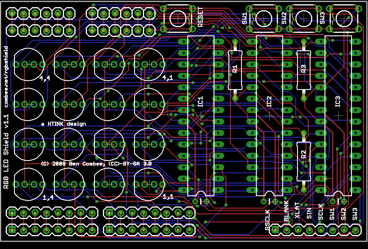
Version 1.1
This board was produced in a limited run by Seeed Studio as part of their Propaganda program. I documented the build-out process with several YouTube videos and some posts on The Life Unwired.
RGB_LED_Shield_1.1.zip - includes schematic, board image, and design files for Eagle CAD
HTINK RGB Shield 1.1
by Ben Combee is licensed under
a Creative
Commons Attribution-Share Alike 3.0 United States License.